Series motors basic wiring conguration fig. Airflow direction base on left hand blade installation.
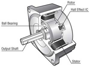 Speed Control Motor Systems Overview
 Learn the procedures thatll save time during the diagnostic process.
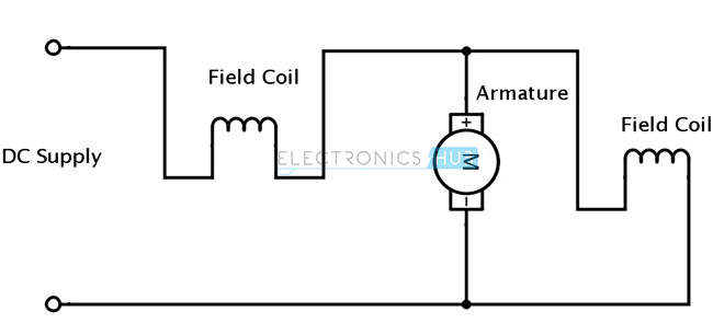
Dc motor internal wiring diagram. Three phase wiring diagrams always use wiring diagram supplied on motor nameplate colored leads are only applicable on the new rolled steel motor lines. Ac single phase washing. 6 curtis pmc 12041205 controller.
Inst maint wiring5qxd 20112015 1137 am page 7. Wiring connect the motor as shown in the connection diagrams. Use figure 2 if your motor has a dual voltage shunt field.
Refer to mn408 for additional details on lead marking. 1o wiring diagrams form b airflow direction base on left hand blade installation. Terminal markings and internal wiring diagrams single phase and polyphase motors meeting nema standards b.
Ac single phase 14 blower motor brushless induction motor 2. If this motor is installed as part of a motor control drive system connect and protect the motor according to the control manufacturers diagrams. A series wound dc motor like in the case of shunt wound dc motor or compound wound dc motor falls under the category of self excited dc motors and it gets its name from the fact that the field winding in this case is connected internally in series to the armature.
When diagnosing a faulty automotive motor it is often impossible not to perform major disassembly such as the fuel pump itself. If a single phase motor is single voltage or if either winding is intended for only one voltage the terminal marking shall be determined as follows. Use figure 1 if your motor has a single voltage shunt field.
Failure to use the double wrench technique could cause undue strain to be placed on the internal connections and could also result in cracked seals around the bus bars. Motor connections your motor will be internally connected according to one of the diagrams shown below. Motor wiring diagram dc.
Curtis pmc 12041205 manual. I show how to wire several different types of motors and explain some of the important components. Airflow airflow airflow airflow these diagrams are current at the time of publication check the wiring diagram supplied with the motor.
Overload relays ac motors dc motors wiring capacitors resistors semiconductors table 1 standard elementary diagram symbols contd iron core air core auto iron core air core current dual voltage thermal magnetic single phase 3 phase squirrel cage 2 phase 4 wire wound rotor armature shunt field show 4 loops series field show 3 loops. The wiring fusing and grounding must comply with the national electrical code. These connections are in accordance with nema mg 1 and american standards publication 06.
 Dc Motor Technology And History
 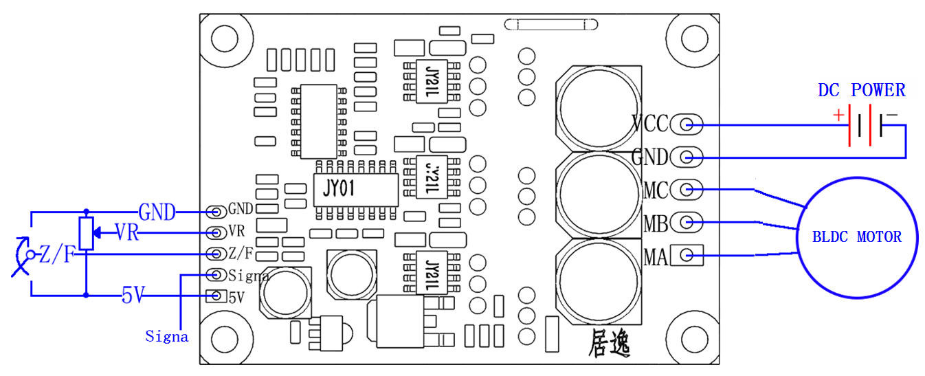 Pwm 12v Brushless Motor Controller 15a 12v Dc Motor
  The Direct Current Motor University Physics Lecture Series
 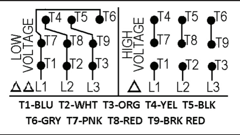 Motor Wiring Part 2 Ec M
 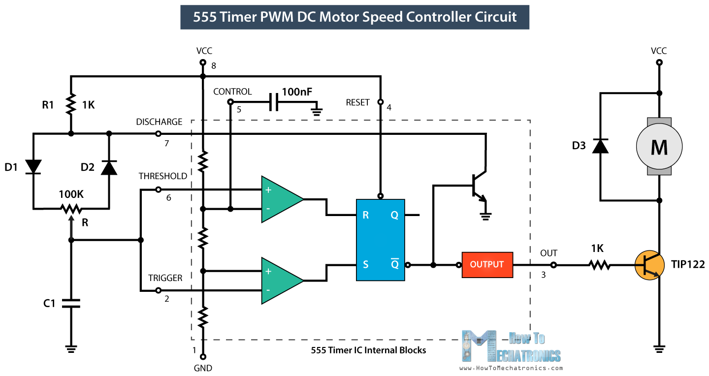 Dc Motor Controller Schematic Wiring Schematic Diagram
  Dc Motor Types Brushed Brushless And Dc Servo Motor
 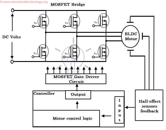 What Is Brushless Dc Motor Bldc Structure Working
 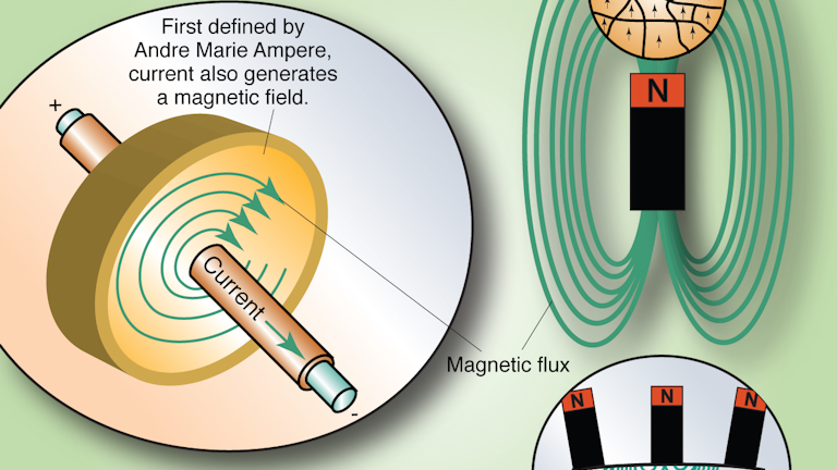 What S The Difference Between Ac Induction Permanent Magnet
 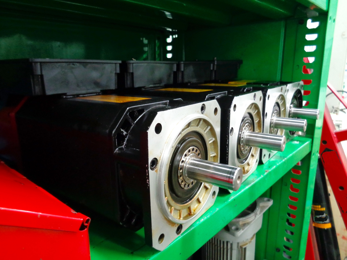 An Intro To The Four Types Of Dc Motors Motion Control Blog