Pneumatic symbols only when the design fails does it draw attention to itself. When it succeeds its invisible.
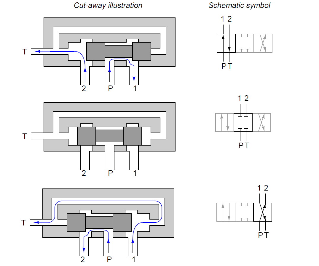 Diagram For Solenoid Symbols Wiring Diagram
 Circuit symbols are used in circuit diagrams showing how a circuit is connected together.
Circuit diagram symbol solenoid. We will understand why it is designed so once after taking a look at the complete circuit. Relay symbols and electromagnets. The relay are switching devices activated by signals.
Hydraulic solenoid valve wiring diagram collections of wiring diagram symbol solenoid simple hydraulic solenoid valve. To build a circuit you need a different diagram showing the layout of the parts on breadboard for temporary circuits stripboard or printed circuit board. Free electrical electronic pneumatic and hydraulic symbols library with dxf dwg and visio formats ordered by categories.
A very first appearance at a circuit layout may be complicated however if you could check out a subway map you. Howeverdifferent parts schematic symbols are used to show whole component and how these work. Understanding ansi iso schematic symbols for fluid power and pneumatic components are used to identify and graphically denote the function and operation of piped control systems.
In this topic we are talking about how the hydraulic schematic symbol for control valve is derived. The complete circuit diagram for solenoid driver circuit is shown in the image below. As you can see the circuit is very simple and easy to build hence we can test this using a small breadboard connection.
Most of the time a small voltage or current is used to switch other voltages or higher currents that may be electromechanical or fully electronic type. The actual layout of the components is usually quite different from the circuit diagram. Berry all the symbols you need to design your pneumatic circuit in dxf format.
Symbols show the methods of actuation the number of positions the flow paths and the number of ports. Scan through and easily download the one you need. This is a very simple animated illustration on the basics of hydraulic schematic symbols.
Here is a brief breakdown of how to read a symbol. Solenoid valve and common pneumatic system symbols. A newbie s overview of circuit diagrams.
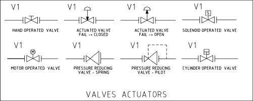
Pneumatic circuit symbols representing these valves provide detailed information about the valve they represent. The symbols are designed to make it easy to understand the most of hydraulic and pneumatic components. Gas solenoid valve wiring diagram simple hydraulic solenoid valve.
Pneumatic circuit valve symbols.
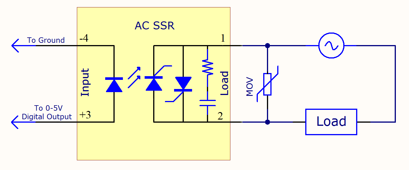 Ssr Ac Schematic Wiring Diagram 500
 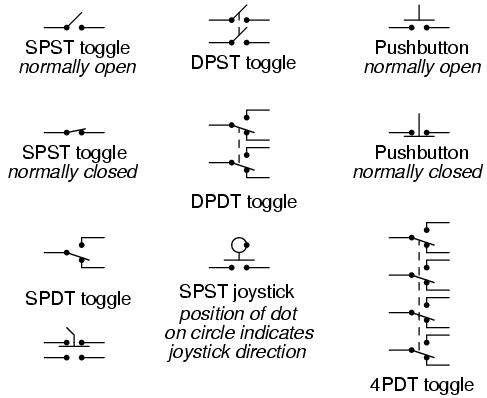 Switches Hand Actuated Circuit Schematic Symbols
  Diagram Comparison Of Iec Nema Schematic Diagrams Diagram For Solenoid Symbols Wiring Diagram
 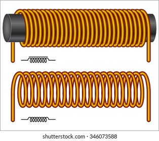 Inductor Symbol Stock Vectors Images Vector Art
 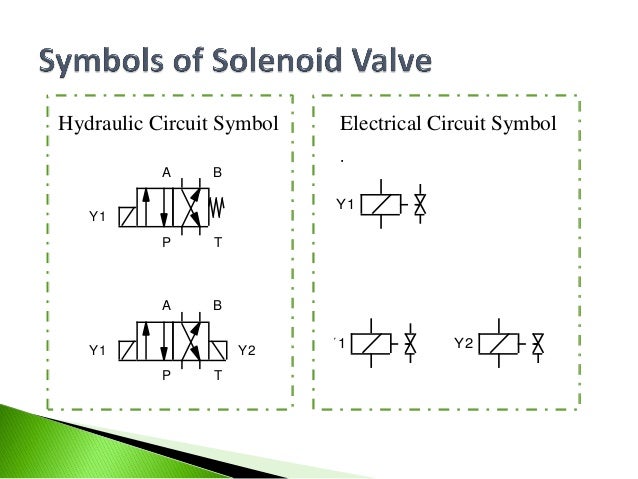 Week 4 2 Basic Of Electro Hydraulics Design
 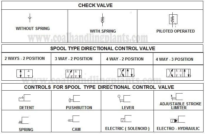 Basic Hydraulic System Components Parts Design Circuit
  Hydraulic Pneumatic Circuit Symbols